I'm trying to set limits for free space on the new (beta) WMI Logical Disk I/O sensor. But it seems that the limit logic is upside-down. What am I missing?
Details: My disk currently has 87% free space. I set the lower warning limit to 50%, the upper warning limit to 30% and the error limit to 10% (in my mind, less free space is bad). However, the sensor immediately shows the disk status as "down". I think it is treating a higher number is "bad" when in fact it is lower numbers that are "bad".
Or is there a trick to setting limits such that higher number are "good" and lower numbers are "bad"? If not, then this is some feedback on the new sensor. Otherwise I love it is replaces several existing separate sensors for me.
Article Comments
You should think about limits as about car wheel pressure gauge:
| Gauge level | Gauge zone | Represents |
|---|---|---|
| Very low and very high | Red | Very high emergency risk |
| Medium low and medium high level | Yellow | Warning about problem |
| Zone between medium low and medium high level | Green | That's all OK |
Sep, 2016 - Permalink
Thank you. I see now that the root cause was that I didn't scroll down in the "Edit Channel" window, and did not see the lower error limit box. So I misinterpreted the upper and lower warning limits.
It makes much more sense now.
Sep, 2016 - Permalink
Thank you Oleg,
we appreciate your metaphor, its a great explanation for limits.
What you've described would look somewhat like the following in PRTG:
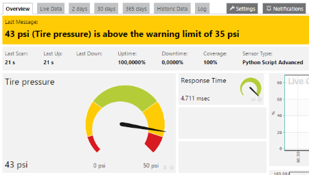
Best regards,
Sebastian
Sep, 2016 - Permalink
Greetings all, the explanation on how to set limit is made clear to me with this demonstration, pls kindly givem me a screen shot on how to set this limit on the channel IDs with the corresponding figures. how did you do this?
Dec, 2016 - Permalink
Dear Frank,
May I kindly ask to further clarify what you mean by "corresponding figures"? What is unclear after looking at PRTG's definition of channel limits?
Best,
Sebastian
Dec, 2016 - Permalink
Hello Sebastin,
it was difficult for me to undertand the Lower Warning Limit, Lower Error Limit, Upper Warning Limit and Upper Error Limit terminology and when and which to apply to a particular sensor, from the figure above I was able to understand the concept using this technique, assuming the parameters I mentioned above stands for LWL and LEL, UWL and UER, if you place them on the analogue meter above as it appears on the Tire Pressure Gauge Sensor, LEL = Yellow, LWL =Red and UWL stands for Yellow, UEL stands for Red, while the Green stands for 'Best Performance' level..... what of a situation when we don't need to define the entire 4 parameters like LEL and LWL, UWL and UER, what of an Exchange Server sensor like MSExchangeIS: Active User Count, MSExchangeIS: RPC Requests, SMTP name them just like Sensors that requires two states up is good while down is bad or UP is Bad while down is good?
Thank you.
Dec, 2016 - Permalink
Dear Frank,
Thank you for your clarification. You don't have to define the four different limits at once. If you just need one or two different states you are free to define them.
The following example displays the channel limits of a WMI Free Disk (Multi Disk) sensor. As you can see there is just a lower warning limit and a lower error limit defined.

Best,
Sebastian
Dec, 2016 - Permalink

Hello, I think you have to set 30% as lower warning limit and 10% as lower error limit
Sep, 2016 - Permalink